

Most calibration problems don’t start where people think
When measurement results become unstable, the first reaction is usually:
- “The CMM may need adjustment.”
- “The scanner accuracy is drifting.”
- “Software compensation is wrong.”
Sometimes that’s true.
But in a lot of real setups, the problem starts much earlier — with the calibration artifact itself, or with how it’s being used.
That part gets underestimated all the time.
A calibration artifact is supposed to be the “known good geometry” in the system. If that reference is unstable, damaged, poorly selected, or simply used in the wrong way, the rest of the measurement chain becomes difficult to trust.
And this happens more often than many people want to admit.
Calibration artifacts are not just reference tools
On paper, calibration artifacts are simple:
They provide known geometry for calibration and verification.
But in actual production environments, they end up doing much more than that.
They reveal things like:
- volumetric drift
- probe behavior
- alignment instability
- thermal influence
- reconstruction inconsistency
- repeatability problems
This is why experienced engineers usually care less about the certificate itself, and more about how the artifact behaves over time.
Because stable geometry matters more than impressive specifications.
Why spheres became the standard
There’s a practical reason spheres are used everywhere in metrology.
Not because they are easy to manufacture — high precision spheres are actually difficult to produce consistently.
The real reason is that spheres behave predictably during measurement.
Compared to edges or planes:
- they are easier to probe
- easier to scan
- easier to fit mathematically
- less sensitive to orientation
That last point matters more than people realize.
A plane can look different depending on alignment.
A sphere is much more forgiving.
That’s one reason spheres are heavily used in:
- CMM calibration
- 3D scanner calibration
- industrial CT systems
- optical metrology
- robotic measurement systems
Especially in scanning systems, spheres make reconstruction easier because fitting algorithms remain relatively stable even when point density changes slightly.
That’s not true for many other geometries.
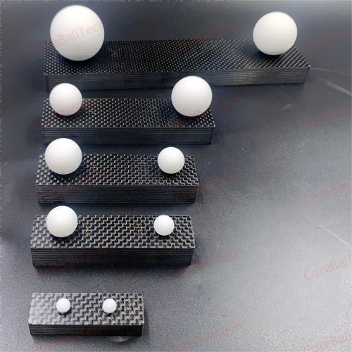
The simplest artifact — calibration balls
Most engineers start with a calibration ball because it’s simple, fast, and practical.
And honestly, for many setups, that’s enough.
A good calibration ball works well for:
- probe verification
- local geometry checks
- scanner validation
- quick repeatability tests
You’ll see them everywhere because they are easy to integrate into daily measurement routines.
But this is where people sometimes misunderstand their limitation.
A single sphere can only tell you what’s happening locally.
You may get excellent fitting on one calibration ball while the system is still drifting badly across space.
This becomes obvious in larger CMM systems or wide-area scanning setups.
A local result is not the same as a system result.
Those two things get mixed together constantly.
Why ball bars become necessary
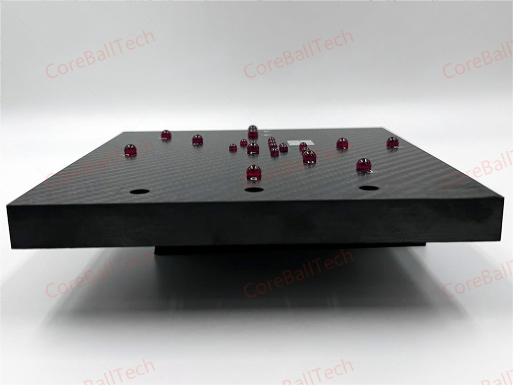
This is usually the point where engineers move to ball bars.
Not because ball bars are “more advanced,” but because they reveal a different type of error.
A ball bar allows you to evaluate:
- center distance behavior
- alignment consistency
- spatial positioning
- volumetric accuracy
That changes the entire conversation.
With a single sphere, you mainly evaluate geometry.
With a ball bar, you start evaluating how the machine behaves between points.
That difference matters a lot in production systems.
Especially when:
- measuring larger parts
- scanning across wide volumes
- combining multiple coordinate systems
- checking robotic motion
This is where some systems start looking accurate locally, but inconsistent globally.
A ball bar exposes that very quickly.
Ball plates tell an even bigger story
For optical systems and 3D scanners, ball plates usually provide more useful information than single spheres.
A ball plate introduces spatial geometry across multiple directions simultaneously.
That makes it easier to identify:
- distortion
- scaling problems
- reconstruction drift
- alignment instability
And unlike simple grid targets, spheres remain easier to fit reliably.
That’s one reason ball plates are widely used in:
- structured light systems
- laser scanning systems
- industrial CT
- automated optical inspection
But more geometry also means more variables.
This is something many people overlook.
A complicated artifact does not automatically improve calibration quality.
If the setup itself is unstable, additional geometry can actually make troubleshooting harder.
Surface finish matters more in optical systems
This is one of those details people often ignore at the beginning.
Then later they wonder why scanning results look noisy.
For CMM probing, polished spheres usually work well because contact behavior is stable.
But optical systems behave differently.
Highly reflective surfaces create problems such as:
- scattered light
- unstable edges
- missing point cloud regions
- inconsistent reconstruction
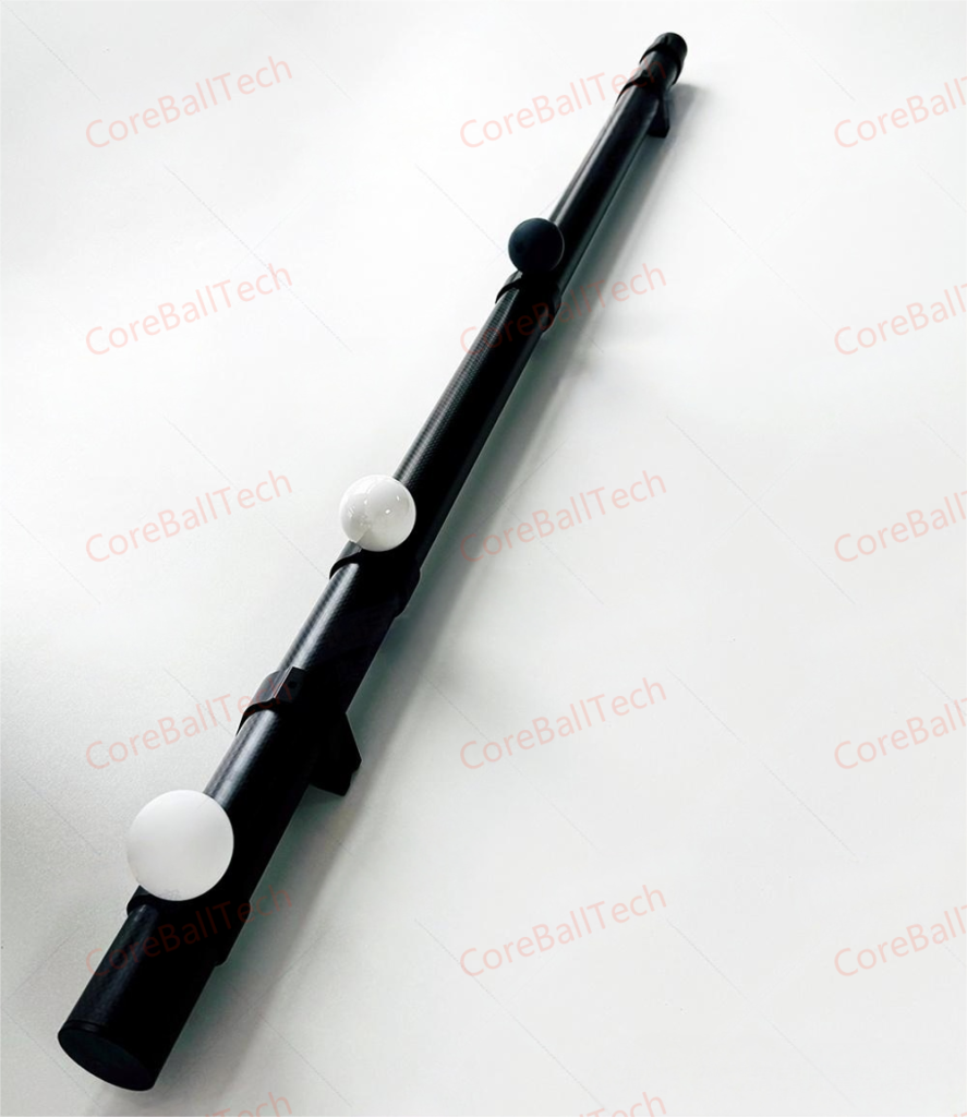
That’s why matte or diffuse surfaces are commonly used for 3D scanner calibration artifacts.
The difference becomes especially obvious when scanning from multiple angles.
A polished sphere may look visually “higher quality,” but scanning systems often disagree.
Material choice is not only about hardness
People often compare materials only by hardness or wear resistance.
In practice, thermal behavior becomes equally important.
Steel is common because it’s cost-effective and mechanically stable.
But steel also reacts more to temperature change than many users expect.
Ceramic tends to remain more stable in long-term calibration environments.
That’s one reason ceramic spheres are common in higher-end metrology applications.
Carbide provides excellent rigidity and wear resistance, but weight sometimes becomes a problem in larger setups.
There is no perfect material.
Usually the right choice depends on:
- environment
- measurement cycle
- required stability
- system type
Measurement strategy changes the result more than people think
A lot of users follow standard measurement routines without really questioning them.
The classic example is the 25-point sphere measurement method.
Yes, it works.
But what matters is not only the number of points.
Distribution matters more.
If the point pattern is poor, adding more points often just repeats the same error.
This becomes obvious in scanning systems where point density is uneven.
In real setups, experienced engineers often adjust point distribution depending on:
- sphere size
- probe accessibility
- scanner angle
- suspected error region
Sometimes fewer well-distributed points produce cleaner fitting than dense but poorly distributed data.
That part rarely gets mentioned in textbook explanations.
Most bad calibration results come from small problems stacking together
People usually expect one obvious failure.
In reality, calibration issues are often cumulative.
Small effects start interacting:
- slight temperature drift
- imperfect fixture stability
- probe wear
- airflow
- uneven scanning angle
- poor point distribution
Individually, none of them look dramatic.
Together, they create unstable results.
This is why repeatability matters so much.
A system producing slightly imperfect but repeatable data is usually easier to trust than one producing “perfect” numbers inconsistently.
Production environments care about stability more than isolated performance.

CMM systems and 3D scanners fail differently
This is important.
People often apply the same calibration thinking to both systems, but the dominant errors are different.
In CMM systems, problems usually come from:
- probe calibration
- stylus behavior
- axis geometry
- thermal expansion
- machine mechanics
In 3D scanners, errors are more likely related to:
- point cloud reconstruction
- optical distortion
- alignment drift
- sensor noise
- lighting conditions
Same artifact. Different failure mechanisms.
That’s why a setup that performs well on a CMM can still behave poorly in scanning applications.
What experienced engineers actually look for
Not perfect numbers.
Usually they care more about questions like:
- Does the system drift over time?
- Do errors repeat in the same direction?
- Does alignment stay consistent?
- Does the artifact behave predictably after repeated use?
- Does the system remain stable across the full volume?
Those questions tell you much more about the real condition of the measurement system.
Final thoughts
Calibration artifacts are not just accessories sitting beside the machine.
They are the reference geometry that defines whether the measurement result means anything at all.
And in real metrology work, the goal is rarely “perfect accuracy.”
Usually the real goal is simpler:
- stable measurements
- repeatable behavior
- predictable system performance
Because once measurements become inconsistent, even small errors become difficult to trust.
That’s where good calibration practice starts to matter.