

Introduction
In precision metrology, especially for portable coordinate measuring machines (Portable Arm CMMs), calibration artifacts such as calibration spheres and ball bars play a critical role in ensuring measurement accuracy and system reliability.
These artifacts are widely used for:
- Probe calibration
- Single-axis verification
- Volumetric accuracy evaluation
- System performance validation
This article provides a structured overview of their specifications, applications, and calibration methods.
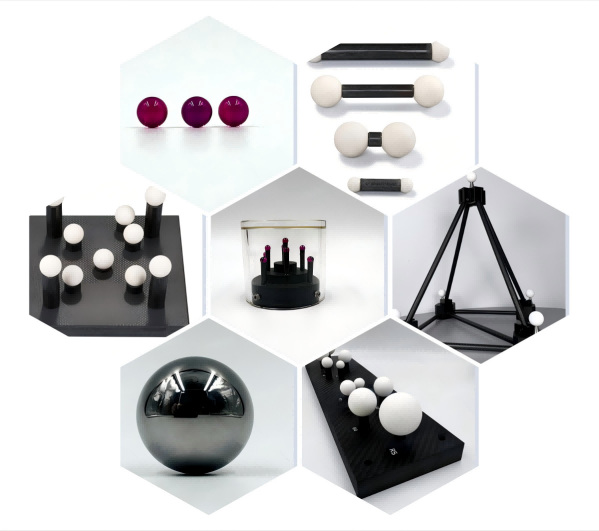
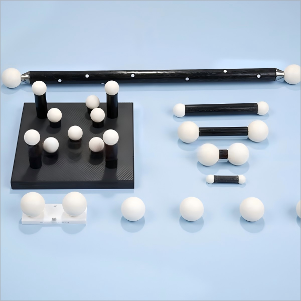
Calibration Sphere & Ball Bar Specifications
Calibration Sphere
High-precision calibration spheres are designed to provide stable geometric references for probing systems.
Typical Specifications:
- Sphericity: ≤ 1.0 μm
- Diameter tolerance (MPE): ±1.0 μm
- Material options: Ruby / Ceramic / Silicon Nitride (customizable)
These spheres ensure high repeatability and are essential for accurate probe qualification.
Ball Bar (Standard Sphere Rod)
Ball bars are used to evaluate distance measurement accuracy within the working volume of a measuring arm.
Key Requirement:
- Expanded uncertainty (U): ≤ 1/4 MPE of the arm’s maximum permissible length error
This ensures the ball bar is significantly more accurate than the system being tested.
Standard Cone & Trihedral Socket
Geometry Requirements
Cone features are commonly used for calibration due to their ability to constrain probe movement precisely.
- Diameter: 10 mm – 15 mm
- Cone angle: 60° – 120°
- Depth: ≥ 1/3 of probe ball diameter
- Surface roughness: Ra ≤ 0.8 μm
These parameters ensure stable contact and repeatable probing results.
Portable Arm CMM: System Overview
A portable articulated arm CMM is a coordinate measurement system based on multiple rotary joints and angular encoders.
Structure:
- Shoulder joint: A & B axes
- Elbow joint: D axis
- Wrist joint: E axis + terminal rotation
Typical configurations include:
- 5-axis
- 6-axis
- 7-axis systems
The probe position is calculated through coordinate transformation of joint angles.
Calibration Methods
1. Single-Axis Coordinate Consistency
Two common methods are used:
- Cone-based calibration
- Sphere-based calibration
Recommended Setup
To fully utilize encoder range, calibration artifacts should be placed at at least three positions within the working volume:
- D ≈ 20% R
- D ≈ 40%–60% R
- D > 80% R
Where:
- D = distance from artifact to arm base
- R = measuring radius
Positions should be evenly distributed across 360°.
2. Cone Calibration Method
Procedure:
- Move the arm approximately 180° horizontally
- Rotate the wrist joint about 90°
- Keep the probe continuously in contact with the cone center
- Record ≥10 measurement points per cycle
- Repeat at least 3 cycles
Result Evaluation:
- Calculate half of the difference between max and min values per cycle
- Take the maximum value across cycles as the final result
3. Probe Qualification (Single-Point Method)
Recommended method:
- Use a cone with 10–15 mm diameter
- Place at 50%–60% of measuring radius (R)
- Measure from four directions (front/back/left/right)
- Collect 5 points per direction
- Angle between points: ~20°
Results must comply with manufacturer specifications before applying probe compensation.
Volumetric Length Error Verification
Ball Bar Selection
Two calibrated ball bars are required:
- Short bar: L = 50%–70% R
- Long bar: L = 120%–150% R
Measurement Strategy
The working volume is divided into quadrants:
- Sphere centered at shoulder joint
- Radius = measuring range (R)
- Installation plane = equatorial plane
Measurement Conditions:
Orientation:
- Horizontal
- Vertical
- 45° inclined
Position:
- Above / below equatorial plane
Distance:
- Near (<50% R)
- Far (>50% R)
Direction:
- Radial (through center)
- Tangential (off-center)
Data Collection
For each measurement:
- Measure ≥5 points per sphere
- 4 points on equator
- 1 point at pole
- Calculate center distance
- Repeat 3 times per position
Final volumetric length error is calculated based on measurement deviations.
Conclusion
Calibration spheres and ball bars are essential tools for ensuring the accuracy, repeatability, and traceability of portable CMM systems.
By following standardized calibration procedures and using high-precision artifacts, manufacturers and metrology engineers can significantly improve measurement reliability across industrial applications.