

Quick Answer
A precision ball bar can be used as a geometric reference for evaluating the measurement performance of a 3D scanner or coordinate measuring system.
The measurement is not simply about checking the diameter of the balls.
By scanning the reference spheres and fitting the measured points to theoretical spheres, engineers can evaluate sphere diameter, sphere form error, sphere-center position, and center-to-center distance.
These results provide a practical way to understand how accurately the measurement system is capturing known geometric relationships.
What does a ball bar actually measure?
A ball bar normally contains two or more precision spheres mounted at defined positions.
The basic reference is the relationship between the spheres.
For example, if the distance between two sphere centers is known, the scanner can measure both spheres and calculate the distance between their fitted centers.
The difference between the measured value and the reference value provides information about dimensional accuracy.
However, before the center-to-center distance can be calculated, the scanner first needs to correctly measure the individual spheres.
That is why sphere diameter and form are also important.
Start with the sphere surface
When using a ball bar for optical measurement, the scanner captures a point cloud from each sphere.
The point cloud contains the measured surface coordinates.
In a typical measurement procedure, multiple points are distributed over the sphere rather than measuring only a few locations.
One practical approach is to use 25 measurement points on each sphere.
The points can be distributed around different latitude angles so that the measurement covers the sphere surface from several directions.
The exact distribution can be adjusted according to the measurement system and the applicable procedure.
The important principle is to obtain a sufficiently representative point distribution for sphere fitting.
Why avoid the ball stem?
When measuring a mounted sphere, the area near the connection or stem should normally be avoided.
The stem is not part of the spherical surface being evaluated.
If points close to the mounting area are included in the calculation, they may affect the sphere-fitting result.
This is especially important for optical scanning because the transition between the sphere and its support can also produce unwanted or incomplete point data.
A clean measurement area produces a more reliable fitting result.
Fitting the measured points to a sphere
Once the point cloud has been collected, the next step is geometric fitting.
The measured coordinates are used to calculate a theoretical sphere that best represents the measured data.
A least-squares sphere fitting method is commonly used for this type of evaluation.
The fitting process produces key parameters such as:
- sphere center coordinates
- sphere diameter
- radial deviations of measured points
These parameters form the basis for the subsequent evaluation.
Sphere diameter
The fitted diameter provides the measured sphere size.
This value can be compared with the certified diameter of the reference sphere.
For example, if the reference sphere has a certified diameter DrD_r and the scanner produces a measured diameter DmD_m, the dimensional deviation can be evaluated from the difference between the two values.
The important point is that the reference sphere itself needs sufficiently accurate dimensional characterization.
Otherwise, it becomes difficult to determine whether the observed error comes from the scanner or the artifact.
Sphere form error
Diameter alone does not tell the whole story.
A sphere can have the correct average diameter while still having measurable form deviation.
After fitting the sphere, the distance from each measured point to the fitted sphere center can be calculated.
The difference between the maximum and minimum radial distances provides an indication of the sphere’s form error under the specified evaluation method.
This is why roundness or spherical form accuracy is an important specification when selecting a precision calibration sphere.
Sphere-center position
The sphere fitting process also produces the center coordinates.
For a single sphere, this gives the measured location of the reference feature.
For a ball bar containing multiple spheres, the center coordinates become more useful because they allow distances between spheres to be calculated.
This is where the ball bar becomes more than a simple sphere measurement tool.
The scanner is now being evaluated on its ability to preserve the spatial relationship between separate geometric features.
Center-to-center distance
Suppose a ball bar contains sphere 1 and sphere 2.
After fitting both spheres, the coordinates of their centers are known.
The distance between the two centers can then be calculated.
If the certified distance is LrL_r and the measured distance is LmL_m, the difference between them provides the distance measurement deviation.
For a ball bar, this is usually one of the most important results.
It directly evaluates whether the measurement system is reproducing a known physical distance correctly.
Why multiple measurements are useful
One scan does not always tell the complete story.
Measurement results can be affected by:
- scanner setup
- temperature
- measurement angle
- point distribution
- operator procedure
- surface condition
- environmental changes
Repeating the measurement under controlled conditions can provide information about repeatability.
If the measured values remain consistent between repeated scans, confidence in the verification result increases.
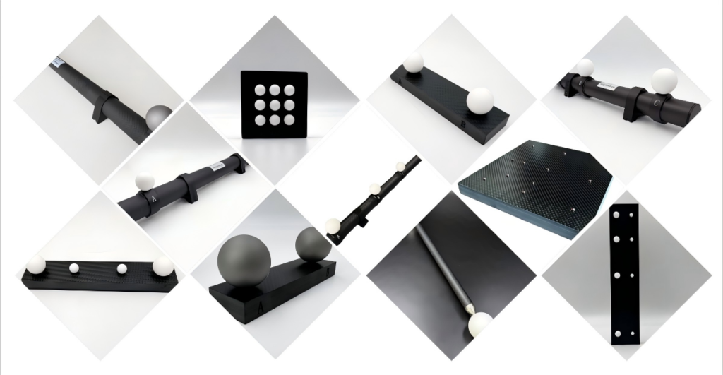
Ball bar for optical 3D scanners
A ball bar can be used with different types of measurement systems, but optical 3D scanning introduces some additional considerations.
The reference spheres need to provide adequate optical contrast and consistent surface acquisition.
For this reason, surface finish can be important.
A polished metal sphere may produce stronger specular reflections under certain conditions.
A matte diffuse ceramic sphere can provide a different optical response that may be more suitable for some structured light measurement systems.
The choice should always be based on the actual scanner.
Ball bar vs. ball plate
A ball bar and a ball plate should not be treated as interchangeable.
A ball bar is particularly useful when the primary reference is a known distance between spheres.
A ball plate contains multiple spheres distributed across a reference structure.
This provides more spatial relationships and can be useful when evaluating larger measurement volumes.
A simple way to think about it is:
Ball Bar → distance reference
Ball Plate → spatial reference network
Both can be valuable, depending on the verification objective.
When a ball bar is a practical choice
A ball bar may be appropriate when:
- the measurement volume is relatively limited
- the main concern is distance accuracy
- a compact reference is preferred
- the measurement procedure focuses on sphere-center distances
- a simple reference artifact is required
It can also be useful as part of a routine verification program.
For a production environment, a compact artifact that can be measured quickly may be easier to use regularly.
What should be specified when ordering a ball bar?
If a customer is purchasing a precision ball bar, I would recommend defining more than the nominal sphere diameter and overall length.
Important specifications can include:
Sphere diameter
The actual diameter and its uncertainty should be documented.
Sphere form
Roundness or spherical form error needs to be controlled.
Center-to-center distance
This is a key reference value for the ball bar.
Sphere-center accuracy
The location of each reference sphere needs to be properly characterized.
Material
Steel, ceramic, carbide, or another material may be selected according to the application.
Surface finish
For optical systems, the surface should be appropriate for the scanner.
Calibration documentation
The reference values should be supplied with appropriate measurement information.
A practical measurement sequence
For an engineering team using a ball bar to check a 3D scanner, the process can be organized into several steps:
1. Stabilize the measurement system
Allow the scanner to reach its normal operating condition.
2. Position the ball bar
Install the artifact according to the verification procedure.
3. Acquire the sphere data
Capture sufficient surface information from each sphere.
4. Fit each sphere
Use the selected fitting method to determine sphere centers and diameters.
5. Evaluate form
Check the radial deviation of the measured points.
6. Calculate center distances
Calculate the distance between the fitted sphere centers.
7. Compare with reference data
Evaluate the measured deviations against the certified values.
This provides a much more useful result than simply looking at the final point cloud.
Where this fits into 3D scanner calibration
It is important to distinguish between calibration and verification.
A ball bar does not automatically replace the manufacturer’s scanner calibration procedure.
Instead, it can serve as a physical reference for evaluating measurement performance.
After calibration, the artifact can be used to determine whether the system is producing the expected geometric results.
This makes the ball bar a useful part of a broader quality-control process.
Final Thoughts
A ball bar is a relatively simple artifact, but the measurement information it provides can be quite valuable.
The process starts with the individual reference spheres.
Their surfaces are measured, the point clouds are fitted to theoretical spheres, and the resulting sphere diameter, form, and center coordinates are calculated.
The center coordinates can then be used to determine the known distances between the spheres.
This creates a direct connection between the physical reference artifact and the measured result.
For 3D scanners and other optical measurement systems, the ball material and surface finish should also be considered because the scanner must first acquire reliable optical data from the reference sphere.
When the objective is primarily distance accuracy, a ball bar can be an effective and practical calibration reference.
When the objective is to evaluate a larger spatial measurement volume, a multi-sphere ball plate may provide more information.
The important thing is not simply choosing a more complicated artifact. It is choosing the reference geometry that matches the actual measurement task.